

The basic properties of copper alloys are largely influenced by the properties of copper itself. Copper is known to
possess certain unique qualities that make it the best engineering material for bearing applications. These are:
- High thermal conductivity
- Excellent ductility and toughness over a wide range of temperatures
- Excellent corrosion resistance in many different environments
Copper’s Atomic Structure
All of the three qualities above are directly related to the structure and behavior of copper’s structure on an atomic
scale.
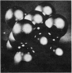
Figure 1. Model of the face-centered cubic crystal structure of copper showing one unit cell.
Distance between centers of corner atoms is 3.6 angstroms (Reference 1).
The copper atom is quite similar to an atom of gold or silver, which together with copper make up a group in the
periodic table of the elements. Everyone is aware of the excellent electrical conductivity of copper, which results from
copper’s atomic structure. Within the copper atom lattice a cloud of free electrons is uniquely available for the
transfer of electrical current. This same cloud of electrons also enhances the efficient transfer of thermal energy.
Solid copper can be described as the arrangement of copper atoms in a face-centered-cubic (fcc) configuration. A copper
atom is found at each corner and in the center of each face of a cube as depicted in Figure 1. This is
the unit cell which is repeated in three dimensional space to make up the crystal structure of the metal.
The atoms are held in place in the structure by the energy of the atomic attractions between them. It is this particular
face-centered cubic arrangement of the atoms that gives copper its high ductility and toughness. All metals deform by
means of a mechanism called slip. When slip occurs, a force on the metal causes the atoms to slide past one another in
groups. In the copper fcc structure this movement occurs preferentially in any or all of three directions along a
specific geometric plane of atoms within the lattice, as shown in Figure 2.
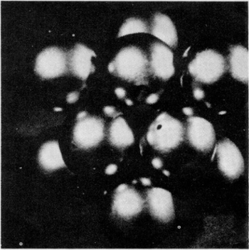
Figure 2. Unit fcc of copper with corner atom removed to show the slip plane on which deformation
preferential takes place. This place embodies the densest atom packing that is geometrically possible (Reference 1).
The copper cell has four such planes. If movement can occur in three directions on all four planes, there are twelve
possibilities for the occurrence of slip. It turns out that this is the maximum number of possibilities for slip found
in any metal structure. The more likely it is that a metal can experience substantial slip, the more likely it is to
deform rather than fracture and fail. Hence, copper has excellent ductility and toughness and is resistant to fatigue
and creep. An added benefit is that copper, since it is a face-centered structure, does not suffer from embrittlement at
low (sub-zero) temperatures; a phenomenon common to other crystal structures.
Copper’s combination of electronic and crystalographic structures imparts its excellent resistance to corrosion. The
free electron cloud is readily available to form coherent films on the metal surface that protect the lattice from
further corrosion.
The fcc structure which generates the slip planes imparts another characteristic to these very planes. The atoms on the
slip planes are packed as closely together as is possible in any metal system (Figure 2). This
efficient arrangement of atoms packs the most matter into a given space (as honeybees seem to know when they build
honeycombs). It is very difficult for hydrogen ions to find their way through the small spaces between the atoms and
cause stress corrosion cracking except in the most aggressive environments.
We have seen how copper, the base metal for cast bronze, when viewed on the atomic scale, imparts the important
characteristics for good bearing materials. But bearings are not made of pure copper, but rather from a wide range of
alloys of copper which are now available. Each of these alloys improves on the performance of pure copper and further
adapts the new material to specific environments. Let us examine some of the more common alloy systems with respect to
the metallurgy of the material and its purpose in bearing design.
Cast Bronze Alloys
The bearing grades of cast bronze can be classified metallurgically into three categories:
- Single-phase solid solution alloys
- Polyphase alloys
- Composite materials
To understand the performance of different alloys, we must first understand what happens to the basic copper structure
when small amounts of alloying metals are added. Reactions occur during the solidification and cooling of alloys from
their molten state.
In simple terms, the final arrangement of the alloying metals with respect to the normal fcc copper lattice determines
the properties of the alloy material.
Alloying metals find their place in the copper lattice in three basic ways:
- They substitute for copper atoms in the fcc lattice.
- They combine with the copper and form localized regions (phases) where the crystal structure is of a form which
differs from the fcc copper crystal. - They are rejected by the solidifying copper lattice but are trapped within the crystals of the alloy as they
freeze and grow.
Research has resulted in the graphical representation of how simple binary alloy systems react. This representation is
called a phase diagram. The phase diagrams of some binary systems relevant to bronze show the behavior of alloying
elements that typically results in one of the three cases mentioned previously. The copper-tin equilibrium phase diagram
(Figure 3) illustrates Cases (1) and (2).
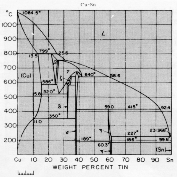
Figure 3. Copper-tin equilibrium phase diagram (Reference 2).
Case (1) – Substitution
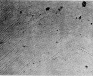
Figure 4. Microstructure of a single-phase (alpha) copper-tin alloy (88Cu-8Sn-4Zn). Structure shows
slip lines. Note also traces of the delta phase (darker islands) (Reference 2).
Referring to Figure 3, at less than 11 % tin (at 8% tin for example), an alloy as it cools is seen to solidify over a
range of temperature, becoming completely solid as the temperature falls below about 850°C. Under equilibrium conditions
of slow cooling, the solid phase that forms is a face-centered cubic crystal (alpha phase). Tin atoms substitute
directly into the lattice in place of copper atoms. The tin atoms have the effect of actually strengthening the pure
copper because they strain the lattice, that is, they alter the usual distance between the copper atoms. Under
commercial conditions of rather slow solidification, nearly all of the metal will solidify as the alpha phase
(Figure 4). This substitutional phenomenon results in a single-phase solid solution of tin in copper.
The crystal structure, though stronger than pure copper due to lattice strain, is still fcc. Consequently, the slip
characteristics remain very good. Single-phase solid solution alloys of copper, therefore, retain high ductility despite
very significant increases in strength. Such materials find wide use under conditions where the material may be
subjected to considerable stress but where fracture would be catastrophic (such as fittings in nuclear reactor seawater
systems).
An example of such a single-phase commerical alloy is alloy C90300, whose properties are compared with copper in the
tabulation below.
| C90300 | ||
|---|---|---|
| Cu | 99.9 | 88.0 |
| Sn | – | 8.0 |
| Zn | – | 4.0 |
| T.S., ksi | 28 | 45 |
| Y.S., ksi | 8 | 23 |
| Elong, % in 2 in. | 45 | 25 |
| Hardness, BHN | 40 | 77 |
| (Values are for continues cast material less than 3 in. in diameter.) | ||
Case (2) – Polyphase
If the tin content is increased to 11% or more, some of the alpha phase will transform as the metal cools below 400°C. A
new phase appears, interspersed throughout the normal fcc alpha crystals. This phase, called delta, can be preserved in
the material with fairly rapid cooling (Figure 5).
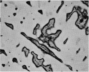
Figure 5. Microstructure of continuous cast tin bronze alloy C90500. Delta phase is indicated (Reference 3).
The delta phase (though still basically fcc) contains much more tin in proportion to copper than is found in the alpha
and is very hard and strong but lacks much ductility. It appears under best conditions as finely dispersed islands
throughout the microstructure of the material. The influence of this second phase on the slip mechanism is dramatic,
having the effect of pinning the slip planes after small degrees of motion. But the delta phase also greatly increases
the wear resistance of the material, as is indicated by the significant increase in hardness. The popular aluminum
bronze alloys (C95400 and C95500) and manganese bronzes (C86300 and C86400) gain their high strength and hardness in a
similar fashion, although the actors are different. Nonetheless, the properties are the result of the dispersion of
another phase (or phases) in the basic fcc lattice with, in nearly all cases, the dispersed phase being much harder and
stronger than the bulk of the surrounding matrix material. These “engineered discontinuities” in the material serve to
anchor the slip planes and restrict their motion.
These materials are known as polyphase alloys and are characterized by higher strength, hardness and wear resistance
than alpha alloys; but they exhibit much less ductility as shown in the tabulation below. As a result, they are best
suited for control surface parts where dimensional integrity is most important and for heavy loads and shockloads under
slow speeds, aircraft landing gear bearings, for example.
An additional characteristic of the polyphase alloys is that their properties can vary with temperature to significant
degrees compared to the single-phase materials. Such alloys are often heat treatable. Through the manipulation of the
microstructure of the alloy as shown on the equilibrium phase diagram by “short circuiting” the equilibrium, certain
properties can be obtained which are absent in the as-cast condition.
| Single-Phase | Polyphase | |||
|---|---|---|---|---|
| C90300 | C90700 | C92500 | C95400 | |
| Cu | 88 | 89 | 87 | 85 |
| Sn | 8 | 11 | 11 | |
| Pb | 1 | |||
| Zn | 4 | |||
| Al | 11 | |||
| Ni | 1 | |||
| Fe | 4 | |||
| T.S., ksi | 49 | 52 | 50 | 85 |
| Y.S., ksi | 23 | 29 | 25 | 35 |
| Elong, % in 2 in. | 25 | 18 | 20 | 18 |
| Hardness, BHN | 77 | 95 | 83 | 170 |
| (Values are for continuous cast material less than 3 in. in diameter, except for C95400 which are for as-cast.) |
||||
In any case, polyphase materials which do not have significant amounts of lead should only be used as bearings against
steel mating surfaces that have themselves been hardened by heat treatment. In the case of aluminum bronze or manganese
bronze applications, it is often recommended that the shaft be chrome plated or made from bi-metal material similar to
that used for steel mill rolls.

Case (3) – Composite Mixtures
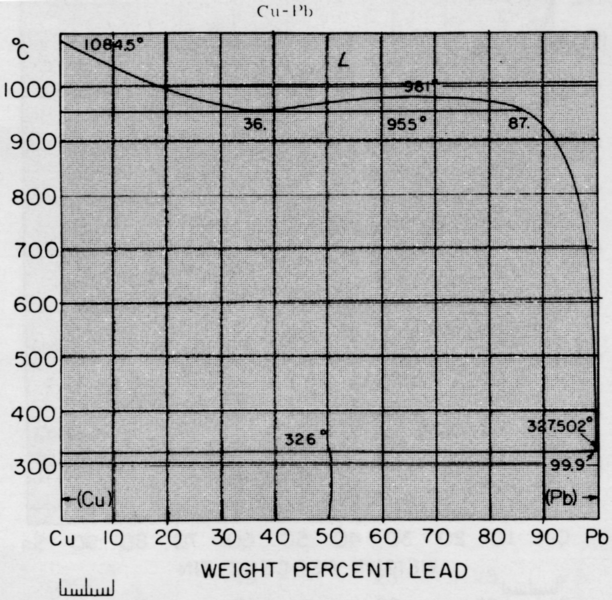
Figure 6. Copper-lead equilibrium phase diagram (Reference 2).
The most widely used bearing materials are really composites. Fundamentally, they can have either single-phase or
polyphase structures serving as a matrix around particles or globules of free lead. A look at the copper-lead
equilibrium phase diagram (Figure 6) indicates that lead is nearly completely rejected by the copper
lattice as it freezes. Nonetheless, metallurgical engineers and foundrymen alike have made great efforts to capture the
lead between the crystals of copper-based material as these crystals freeze and grow because the resultant alloy makes
very fine bearings. A typical microstructure showing the dispersed lead is shown in Figure 7.
Today it is possible to produce copper-base material with lead content in excess of 30%, wherein the size of the lead
particle is microscopic in scale. On the other hand, if the bearing application indicates larger lead particles are more
desirable, it is also possible to produce the alloy in that form.
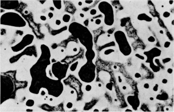
Figure 7. Microstructure of continuous cast leaded tin bronze alloy C94100 (20%Pb). Lead particles are indicated (Reference 3).
Lead performs three important bearing functions, all of which serve to protect the shaft and improve the performance of
the machinery. Of primary importance is the ability of the lead particles to decrease the coefficient of friction
between the bearing and the shaft. The mechanism by which this is accomplished is quite interesting. Lead particles are
free to be sheared off the bearing surface by microscopic rough edges on the shaft surface. The steel shaft becomes
covered with lead which is gradually redistributed to fill in the low spots on the shaft. Once this has been
accomplished, the coefficient of friction rises only slightly again, as indicated in the tabulation below (Reference 4).
This same phenomenon has a further advantage in that the temperature developed at the points of contact between the
bearing and the mated part is limited by the fusion temperature of lead 327, C). Obviously, this property of the leaded
alloys is very valuable in the absence of Lubrication (planned or accidental) or if the operating environment of the
machine is itself subject to wide temperature extremes, for example on aircraft or arctic oil field equipment.
| Coefficient of friction (sliding) |
|
|---|---|
| Steel on Copper | 0.9 |
| Steel on C94300 (23% Pb) | 0.18 |
| Steel on C94300 after extended use | 0.30 |
| Steel on Steel | 1.00 |
The second important function of lead is to absorb dirt which finds its way into the interface, although this problem
can be avoided through the design of properly sealed bearings whenever possible.
Third, leaded alloys, having somewhat lower strength than the non-leaded copper-tin alloys, and much lower strength than
copper-aluminum or copper-zinc alloys, exhibit high degrees of conformability. That is, the bearing will adjust its
shape to allow for poor alignment or for vibration. This characteristic, coupled with those previously described, allows
one to say that the leaded alloys will “wear-in” very well, a particularly desirable feature for worm gears, to name one
example. Lead-containing bronzes are also readily machinable.
The engineer must remind himself that these alloys are not as strong as nonleaded materials, nor do they exhibit as
great a resistance to pounding and subsequent fatigue leading to failure. One comforting consideration, however, is that
total failure of the bearing is not likely to destroy the shaft or seize the machine, due to the “softness” of these
alloys.
By selecting the proper matrix into which the lead particles will be cast, the engineer can select from a fairly wide
range of material strength compatible with moderate to light loads and high speeds, as shown in the tabulation below.
Values are for continuous castings less than 3 in. in diameter.
| C83600 | C93200 | C93700 | C93800 | C94300 | |
|---|---|---|---|---|---|
| Cu | 85 | 83 | 80 | 78 | 70 |
| Sn | 5 | 7 | 10 | 7 | 5 |
| Pb | 5 | 7 | 10 | 15 | 25 |
| Zn | 5 | 3 | |||
| T.S., ksi | 45 | 45 | 41 | 34 | 27 |
| Y.S., ksi | 21 | 24 | 24 | 23 | 13 |
| Elong, % in 2 in. | 28 | 16 | 10 | 12 | 15 |
| Hardness, BHN | 72 | 72 | 80 | 62 | 48 |
Properties of Cast Bronzes
Let us now review the bearing bronze alloy families by means of two tables that compare some of their more important
engineering properties. Table 1 summarizes the chemical compositions and application properties.
Table 2 indicates the more common uses of these materials and their performance qualities in the
application environments in which they find the most use.
| Composition % | ||||||||
|---|---|---|---|---|---|---|---|---|
| Alloy Family | Cu | Sn | Pb | Zn | Ni | Fe | Mn | Al |
| Red brass | ||||||||
| C84400 | 81 | 3 | 7 | 9 | ||||
| C83600 | 85 | 5 | 5 | 5 | ||||
| Leaded Tin bronzes | ||||||||
| C93200 | 83 | 7 | 7 | 3 | ||||
| C93700 | 80 | 10 | 10 | |||||
| High Leaded Tin bronzes | ||||||||
| C93800 | 78 | 7 | 15 | |||||
| C94300 | 70 | 5 | 25 | |||||
| Tin bronzes | ||||||||
| C90300 | 88 | 8 | 4 | |||||
| C90500 | 88 | 10 | 2 | |||||
| C90700 | 89 | 11 | ||||||
| C92500 | 87 | 11 | 1 | 1 | ||||
| C92700 | 88 | 10 | 2 | |||||
| C92900 | 84 | 10 | 2.5 | 3.5 | ||||
| C94700-HT** | 88 | 5 | 2 | 5 | ||||
| Aluminum bronzes | ||||||||
| C95400 | 85 | 4 | 11 | |||||
| C95400-HT | 85 | 4 | 11 | |||||
| C95500 | 81 | 4 | 4 | 11 | ||||
| C95500-HT | 81 | 4 | 4 | 11 | ||||
| Manganese bronzes | ||||||||
| C86300 | 63 | 25 | 3 | 3 | 6 | |||
| C86400 | 59 | 1 | 40 | |||||
| * BTU/ft2/ft/hr/F ** HT – Heat Treated |
||||||||
| Continuous Cast Properties (Typical) | |||||||
|---|---|---|---|---|---|---|---|
| Alloy Family | T.S., ksi | Y.S., ksi | Elong., % |
BHN | Machinability Index |
Compressive Y.S., ksi |
Thermal Conductivity* |
| Red brass | |||||||
| C84400 | 37 | 16 | 23 | 55 | 90 | 28 | 41 |
| C83600 | 45 | 21 | 18 | 72 | 100 | 34 | 41 |
| Leaded Tin bronzes | |||||||
| C93200 | 45 | 24 | 16 | 72 | 100 | 30 | 33 |
| C93700 | 41 | 24 | 10 | 80 | 100 | 25 | 27 |
| High Leaded Tin bronzes | |||||||
| C93800 | 34 | 23 | 12 | 62 | 100 | 23 | 30 |
| C94300 | 27 | 13 | 15 | 48 | 100 | 20 | 36 |
| Tin bronzes | |||||||
| C90300 | 49 | 23 | 25 | 77 | 25 | 36 | 43 |
| C90500 | 51 | 29 | 18 | 92 | 25 | 29 | 43 |
| C90700 | 51 | 29 | 18 | 95 | 20 | 38 | 41 |
| C92500 | 49 | 26 | 17 | 80 | 30 | 32 | 42 |
| C92700 | 48 | 20 | 18 | 80 | 80 | 28 | 40 |
| C92900 | 53 | 31 | 15 | 100 | 85 | 38 | 34 |
| C94700-HT** | 90 | 66 | 9 | 180 | 20 | 71 | 31 |
| As-Cast Properties | |||||||
| Aluminum bronzes | |||||||
| C95400 | 85 | 35 | 18 | 170 | 60 | 50 | 34 |
| C95400-HT | 105 | 54 | 8 | 195 | 20 | 75 | 34 |
| C95500 | 100 | 44 | 12 | 195 | 50 | 60 | 24 |
| C95500-HT | 120 | 68 | 10 | 230 | 15 | 80 | 24 |
| Manganese bronzes | |||||||
| C86300 | 115 | 70 | 15 | 225 | 8 | 80 | 20 |
| C86400 | 65 | 25 | 20 | 90 | 65 | 40 | 51 |
| *BTU/ft2/ft/hr/F **HT – Heat Treated |
|||||||
| Qualitative Bearing Operating Environment | |||||
|---|---|---|---|---|---|
| Alloy No. | Speed | Load | Environment | Shaft Hardness | Typical Applications |
| C94300 | (Low)
|
(Lower)
|
(More Abrasive) (Less Abrasive) |
(Low)
|
Aircraft Fuel Pumps |
| C93800 | Mine Water Pump, Wear Plates | ||||
| C93700 | Heavily Loaded High-Speed Bearings | ||||
| C93200 | General Purpose Bearings | ||||
| C83600 | Deep -Well Pump Line Shaft Bearings, Light Duty Gears | ||||
| C92700 | Piston Rings | ||||
| C90500 | Gears, Valve Guides, Pump Impellers | ||||
| C92900 | Gears, Valve Guides, Steel Back Substitute | ||||
| C90300 | Valve Components, Steam Fittings | ||||
| C90700 | Gears | ||||
| C95400 | Control Surfaces | ||||
| C95500 | Control Surfaces | ||||
| C86300 | Rolling Mill Screw Down Nuts | ||||
All of the alloys shown in the tables are essentially variations of the fundamental materials which have been discussed.
In some cases, lead may have been added to improve machinability (C92500 vs. C90700). Perhaps nickel has been added to
increase strength or corrosion resistance (C95500 vs. 95400). Manganese and iron content may be varied to stabilize
certain structures (C86300 vs. C86400). Zinc may have been substituted for tin for the sake of economy (C90500 vs.
C90700). One alloy was created out of the prevailing availability of scrap materials (C93200 from C83600 and C93700) and
is now perhaps the most widely used bearing alloy. It is a very good compromise. Nonetheless, each material has a unique
set of properties that will best fit some particular appreciation.
Economics
A few words about the relative economics of the alloy materials are important. All of the alloy components are subject
to the influence of world markets, where their price levels are determined by supply, demand, government controls and
speculative interest. Fluctuations in the world market for these components ultimately find their way into the composite
metal cost for the alloys and this also influences the scrap value of the material when it is removed from service.
Table 3 shows the approximate general relative values of copper and the principal alloying materials,
at the time this was written.
| Approximate Relative Cost |
Approximate Relative Cost |
||
|---|---|---|---|
| Primary Metals | Secondary Scrap | ||
| Copper | 1.0 | Leaded Tin bronze | 0.9 |
| Tin | 7.8 | Tin bronze | 1.0 |
| Lead | 0.2 | Aluminum bronze | 0.3 |
| Zinc | 0.5 | Manganese bronze | 0.3 |
| Nickel | 4.0 | ||
| Aluminum | 0.9 | Pre-Alloyed Ingot | |
| C93200 | 1.2 | ||
| C90700 | 2.0 | ||
| C98400 | 1.2 |
Manufacturing Methods
The bearing grade alloys of copper are available in many forms produced by various methods of manufacture. Cast
production methods are summarized in Table 4.
Sand and Chill Mold Products
| Production Method | |||||
|---|---|---|---|---|---|
| Alloy Family | Sand | Chill Mold |
Centrifugal | Continuous | Wrought |
| Red brasses | X | X | X | X | N/A |
| Leaded Tin bronzes | X | X | X | X | X* |
| High Leaded Tin bronzes S=Pb segregation can be a problem | S | S | S | X | N/A |
| Tin bronzes | X | X | X | X | X** |
| Aluminum bronzes | X | X | X | X | X |
| Manganese bronzes | X | X | X | X | X |
| * Limited to about 4% Pb **Wrought alloys C51000, C52100, C52400. |
|||||
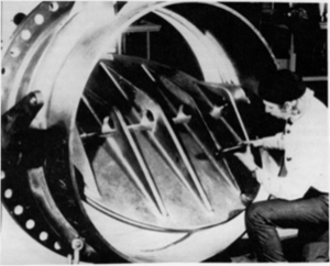
Casting in sand or chill molds are ideal production methods ideal for very small runs or very small parts and are
sometimes mandatory for very large parts such as ship propellers.
All of the alloys discussed are available in these forms, although problems with severe lead segregation may occur as
the lead content approaches 16%. A wide range of sizes and intricate shapes can be cast. The red brasses, which are very
popular as plumbing hardware materials, are produced by these methods, mainly in the form of valve bodies and fittings.
Centrifugally Cast Products
Again, all subject alloys are readily produced by the centrifugal casting method, with the exception of high-leaded tin
bronzes in which the lead content approaches 20%. Lead segregation problems are sensitive to the size of the casting.
Very large bushings are manufactured by this method. It is likely that most bushings over 14 in. O.D. and up to about
100 in. O.D. are centrifugal castings. Such castings can be made in lengths that exceed 100 in. Nevertheless, small
centrifugal castings are also high-volume items. Many of the larger flanged bearings or gear blanks are manufactured by
this method. Though sensitive to production quantity, small runs can be very economical. Stocking distributors maintain
inventories of semi-finished centrifugal castings, primarily in standard sizes and especially in alloys C95400 and
C93200.
Continuous Cast Products
All alloys are available as continuous cast barstock; lead segregation is generally not a problem. It may be necessary
to stress relieve certain castings with very thin walls, particuarly if the alloy is C95400, C95500 or C86300, to
prevent loss of clearance or tolerance in fabrication and use. A wide size range of solid, tubular and made-to-order
cross section barstock is available. Diameters range from less than 0.500 in. up to about 14 in. in O.D., in lengths up
to about 13 ft. It is possible to produce very thin-walled bars, at times less than 1/4 in., depending on the O.D. These
products are ideally suited for further fabrication using automatic machine tools.
Larger quantities of continuous cast products are considerably more economical, but again stocking distributors absorb a
great deal of this burden, particularly where alloys C95400, C93200 and C90300 are concerned.
Wrought Products
The wrought phosphor bronze alloys (C51000, C52100, C52400, C54400) are sometimes used in bearing applications. These
alloys are also available as continuous castings in the annealed temper. Wrought phosphor bronze is usually limited to
about 3 in. O.D. and under. C54400 has the highest available lead content, about 4%. It is not possible to extrude or
roll alloys with higher lead content.
The aluminum and manganese bronze alloys also have wrought equivalents. The wrought alloys have very strong mechanical
properties, having been severely worked either by extrusion, drawing, rolling or forging and are widely used in
aerospace applications. Some of these alloys are used as weldment materials. These alloys are also available in
different extruded shapes, though the variety available is quite quantity-dependent. Heat treatment of cast alloys
produces mechanical properties similar to the wrought materials, as does the continuous casting of the aluminum bronzes.
Generally speaking, large production quantities are required to make the wrought products economical, although stocking
distributors have assumed this burden for the end-user of smaller quantities.
Finished Bearings
Some producers, as well as many stocking distributors and bearing houses carry inventories of standard finished
bushings, particularly in alloy C93200. These parts are mass-produced and readily available.
Specialty Bearings
A number of machine shops specialize in bearing production, particularly non-standard designs and critical made-to-order
alloys. These shops operate sophisticated machining centers. Using the finest available equipment, they are capable of
the highest degree of precision in part production and maintain high standards of material quality control. Such
establishments serve those OEM establishments and the maintenance departments of larger corporations who choose not to
manufacture their own bearings. They provide economical service and are quite knowledgeable about the technology and
sources of bearing grade alloys that will best suit the production of a given bearing.
Summary
Metallurgical engineering, though very much a science, is also very much an art. Research, extensive experience and a
br/oad understanding of the properties which the alloying elements can impart to the copper base metal are essential to
good material design. Of equal importance is an understanding of the economics associated with the materials, part
production and the operation of the end-use machinery. The remarkable properties of copper, brass and bronze have
benefited industries everywhere through their reliable performance, general availability and economic quality.
References
- R.A. Flinn, Copper, brass and bronze Castings, Non-Ferrous Founders’ Society, Inc., Cleveland
(1961). - R. Hultgren and P.D. Desai, Selected Thermodynamic Values and Phase Diagrams
for Copper and Some of Its Binary Alloys, Incra Monograph I, International Copper Research Association, Inc.,
New York (1971). - W.A. Glaeser and K.F. Dufrane, The Design of Boundary Lubricated Cast bronze
Bearings, Cast bronze Bearing Institute, Inc. (1978). - F. Bowden and D. Tabor, The Friction and Lubrication of Solids, Clarendon
Press, Oxford (1950).